TKC - Tiên Phong về giá trị

Danh mục sản phẩm

Đặt hàng nhanh

Danh mục sản phẩm

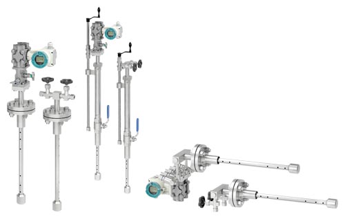
SITRANS FP330/FPS300 AVERAGING PITOT TUBE Overview

Đánh giá trung bình

(5/5)

1 Đánh giá

SITRANS FP330 và FPS300 Averaging Pitot Tube là hai loại cảm biến đo lưu lượng của Siemens, được sử dụng để đo lượng chảy của chất lỏng và khí trong các ứng dụng công nghiệp và quy trình. Cảm biến này dựa trên nguyên lý Pitot-Static để đo lượng chảy một cách chính xác và đáng tin cậy.

Dưới đây là một số điểm nổi bật về SITRANS FP330/FPS300 Averaging Pitot Tube của Siemens:

  1. Nguyên lý đo Pitot-Static: SITRANS FP330 và FPS300 sử dụng nguyên lý Pitot-Static, trong đó cảm biến có cấu trúc dạng đầu đo Pitot để đo tốc độ dòng chảy của chất lỏng hoặc khí, và cấu trúc đo áp suất tĩnh để đo áp suất trong dòng chảy. Từ đó tính toán được lượng chảy của chất lỏng hoặc khí.

  2. Đo lượng chảy dạng trung bình: Averaging Pitot Tube là loại cảm biến đo lưu lượng dạng trung bình, nghĩa là nó sẽ đo lượng chảy trung bình trong một phạm vi lớn hơn so với các cảm biến đo lượng chảy thông thường.

  3. Đa dạng ứng dụng: SITRANS FP330/FPS300 Averaging Pitot Tube có thể được áp dụng trong nhiều lĩnh vực công nghiệp như hóa chất, dầu khí, thực phẩm và đồ uống, năng lượng, và các ứng dụng quy trình khác.

  4. Độ chính xác và đáng tin cậy: Những cảm biến này cung cấp độ chính xác cao và đáng tin cậy trong việc đo lường lưu lượng chất lỏng và khí, giúp người dùng đảm bảo hiệu suất ổn định và hiệu quả của các quy trình công nghiệp.

  5. Hiệu suất ổn định trong môi trường khắc nghiệt: Siemens thiết kế SITRANS FP330/FPS300 Averaging Pitot Tube để chịu được môi trường khắc nghiệt và có khả năng hoạt động đáng tin cậy trong điều kiện công nghiệp.

Tóm lại, SITRANS FP330/FPS300 Averaging Pitot Tube của Siemens là các cảm biến đo lưu lượng sử dụng nguyên lý Pitot-Static để đo lượng chảy của chất lỏng và khí trong các ứng dụng công nghiệp và quy trình. Những cảm biến này cung cấp độ chính xác và đáng tin cậy, giúp giám sát và điều khiển lưu lượng một cách hiệu quả trong các quy trình sản xuất và vận hành.

Số lượng:

+
 

Benefits

  • Easy to retrofit (no rebuilding of the pipe)
  • Easy to install
  • Good for large nominal diameters
  • Wide range of application (media, nominal diameters, process conditions)
  • Minor measurement inaccuracy
  • Special designs possible for special applications
  • Also work in rectangular ducts and pipes

Application

  • Technical Gases
  • Compressed Air
  • Exhaust Air
  • Fresh and Combustion Air
  • Heat Transfer Fluids
  • Water
  • Exhaust Gas
  • Steam/Heat Quantities

Design

Basics: Averaging pitot tubes for flow measurement
  • Mounting by insertion into the pipe (no flange-to-flange instrument)
  • Differential pressure generation through forced flow
  • Variation of the classic "pitot tube" through multiple metering orifices (so-called "averaging pitot tube")
  • Design follows manufacturer guidelines, not standardized
Designs
  • Averaging Pitot Tube for gas and liquids (7ME161)
  • Averaging Pitot Tube for steam (7ME162)
  • Averaging Pitot Tube with FASTLOK (7ME163), to remove sensor during operation without interruption of process
System design
  • Compact design for dry gases and liquids without integrated temperature measurement
  • Compact design for wet gases with or without integrated temperature measurement as well as for dry gases and liquids with integrated temperature measurement
  • Compact design for steam with or without integrated temperature measurement
  • Remote design for dry or wet gases, liquids and steam

Function

Design of the averaging pitot tube

Similar to other differential pressure devices averaging pitot tubes create a differential pressure to measure flow. They are not specified in the general standard ISO 5167, but they follow the same technical principle. In contrast to the classic primary elements, averaging pitot tubes are not "in-line" devices but consist of a "profile" that is inserted into the side of the pipeline.

Differential pressure is created when fluid flows around the profile of the averaging pitot tube. Since the constriction of the pipeline by the profile in relation to the cross-sectional area is much smaller than, for example, with an orifice plate, the created differential pressure and the respective permanent pressure drop are smaller.

The flow comes to a complete stop at the upstream side of the averaging pitot tube creating the upstream pressure. At the downstream side a negative pressure is created by the so-called Kármán vortex street. The differential pressure (difference between upstream pressure and negative pressure) is the measurement signal and is proportional to the flow rate. This results in the following basic formula for flow measurement with averaging pitot tubes:

qm = A • k • √(2 • ∆p • ρ)

qm: mass flow

A: cross-sectional area of the pipe

k: device factor of the pitot tube

∆p: differential pressure

ρ: density

The k-factor is the device factor of the averaging pitot tube and is determined, among other things, by the shape of the profile of the pitot tube. Thanks to the sharp-edged shape of the profile, it remains constant over a very wide Reynolds number range and enables linear flow measurement.

The averaging pitot tube features the same number of measuring openings on the front and back. The special distribution of the measuring openings over the cross section allows geometric averaging in case of uneven flow distribution and thus an accurate measurement even with very short inlet and outlet distances. The generated upstream and downstream pressures are averaged in the respective chambers and routed to the differential pressure transmitter.


Technical specifications

SITRANS FP330/FPS300

General design


Working principle

Multi-port averaging pitot tube for round and rectangular pipes

Media

  • Steam (saturated, superheated)
  • Gas (dry, up to 100% water saturated)
    (automatic purging unit for high dust applications on request)
  • Liquids (water, non-conductive liquids, oil, etc.)

Transmitter installation

  • Compact mount with differential pressure transmitter
  • Remote mounted differential pressure transmitter

Bidirectional flow

Yes (symmetric sensor design)

Calculation

According to manufacturer standard

Accuracy


Linearity

(of Sensor k-Factor)

Re > 20 000: 1%

Repeatability

(of Sensor k-Factor)

Re > 20 000: 0.1%

Measurement range

Typically, up to 1:10

(real measurement range depends on transmitter performance)

Operating conditions


Pressure

Flange: Max. PN 100

Cutting Ring: Max. PN 40 (max. 180 °C)

FASTLOK: Max. PN 16 (max. 180 °C)

(higher pressure ratings on request)

Temperature

Stainless Steel sensor: -100 ... 500 °C

16Mo3: -20 ... 530 °C

Alloy: -20 ... 700 °C

(exact maximum temperature depends on sensor design, feasibility will be calculated by sizing tool)

Pressure loss

generally, <10% of differential pressure

Installation conditions


Straight inlet diameter

7 × Inner diameter behind 90° elbow

Straight outlet diameter

3 × Inner diameter

(for detailed calculation of recommended installation pipe length please refer to sizing tool or manual)

Design


Material sensor

Standard: Stainless steel 1.4404/ AISI 316L

Optional: 1.5415/16Mo3, Alloy C22

(other materials on request)

Diameter

40 ... 4000 mm

(larger sensors on request)

Material mounting parts

Standard: Carbon steel

Optional: Stainless Steel 1.4404 / AISI 316L

(other materials on request)

Process connection

Flange EN 1092-1 B1

Flange ASME B16.5 RF

Cutting Ring fitting

FASTLOK (retractable design)

(other process connections on request)

Thickness of pipe insulation

0 ... 200 mm

Approvals


Hazardous area

(see differential pressure transmitter)

Enclosure rating

(see differential pressure transmitter)

Operational safety

(see differential pressure transmitter)

QAL1, SIRA


Accessories

Z-Options for Cable Glands, Plugs, Labeling, Approvals, blanking plugs, flangs seals, device settings, etc. according to SITRANS P320


Options

Further versions that are available on request:

  • Weld-in sensor for high pressure steam
  • Calibrated metering pipes
  • FASTLOK with flange ball valve
  • Etc.

More information

For more information please see the Installation Instructions and the Instruction Manuals SITRANS P on SIOS.

1 đánh giá SITRANS FP330/FPS300 AVERAGING PITOT TUBE Overview

5

Chọn đánh giá của bạn
Zalo Facebook

Liên Hệ