TKC - Tiên Phong về giá trị

Danh mục sản phẩm

Đặt hàng nhanh

Danh mục sản phẩm

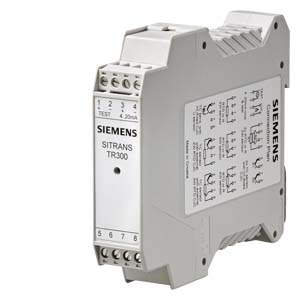
SITRANS TR300 (4 TO 20 MA, HART, UNIVERSAL) Overview

Đánh giá trung bình

(5/5)

1 Đánh giá

SITRANS TR300 (4 to 20 mA, HART, Universal) là một bộ chuyển đổi nhiệt độ của Siemens, được thiết kế để chuyển đổi tín hiệu nhiệt độ từ các cảm biến nhiệt độ thành tín hiệu dòng điện 4 đến 20 mA, và hỗ trợ giao thức HART cho phép truyền thông hai chiều giữa cảm biến và hệ thống điều khiển, giám sát.

Dưới đây là một số điểm nổi bật về SITRANS TR300 (4 to 20 mA, HART, Universal) của Siemens:

  1. 4 to 20 mA Output: SITRANS TR300 chuyển đổi tín hiệu nhiệt độ thành tín hiệu dòng điện 4 đến 20 mA, là một tín hiệu phổ biến trong hệ thống điều khiển và giám sát quy trình công nghiệp.

  2. HART Communication: Bộ chuyển đổi SITRANS TR300 hỗ trợ giao thức HART, cho phép gửi và nhận dữ liệu nhiệt độ thông qua một giao thức truyền thông thông minh. Giao thức HART cung cấp truyền thông hai chiều giữa cảm biến và hệ thống điều khiển, giúp giám sát trạng thái của cảm biến và thực hiện cấu hình từ xa.

  3. Universal Input: SITRANS TR300 được thiết kế với đầu vào "Universal", có thể hoạt động với nhiều loại cảm biến nhiệt độ khác nhau, bao gồm cả RTD và thermocouple, giúp đơn giản hóa quá trình cài đặt và tích hợp vào hệ thống điều khiển và giám sát.

  4. Độ chính xác cao: SITRANS TR300 cho phép chuyển đổi tín hiệu nhiệt độ chính xác và đáng tin cậy trong các quy trình công nghiệp.

  5. Khoảng đo nhiệt độ rộng: Bộ chuyển đổi SITRANS TR300 có thể hoạt động trong khoảng nhiệt độ rộng, phù hợp với nhiều ứng dụng khác nhau.

  6. Tương thích với hệ thống điều khiển: SITRANS TR300 có thể dễ dàng tích hợp vào hệ thống điều khiển và giám sát hiện có của người sử dụng, giúp tối ưu hóa và nâng cao hiệu suất của quy trình.

  7. Ứng dụng đa dạng: SITRANS TR300 có thể được sử dụng trong nhiều ngành công nghiệp và quy trình, bao gồm hóa chất, dầu khí, thực phẩm và đồ uống, và các ứng dụng khác đòi hỏi chuyển đổi tín hiệu nhiệt độ.

  8. Độ tin cậy và bền bỉ: SITRANS TR300 được thiết kế để đảm bảo độ tin cậy cao và tuổi thọ lâu dài, giúp giảm thiểu thời gian dừng máy và chi phí bảo trì.

Tóm lại, SITRANS TR300 (4 to 20 mA, HART, Universal) của Siemens là một bộ chuyển đổi nhiệt độ chất lượng cao, được thiết kế để đáp ứng các yêu cầu đa dạng của khách hàng và đảm bảo hoạt động ổn định và tin cậy trong suốt quá trình vận hành. Chúng là lựa chọn phổ biến trong ngành công nghiệp và quy trình để chuyển đổi tín hiệu nhiệt độ một cách chính xác và hiệu quả.

Số lượng:

+

Overview

Robust and durable HART - the universal SITRANS TR300 transmitter
  • 2-wire device for 4 to 20 mA, HART
  • Device for rail mounting
  • Universal input for virtually any type of temperature sensor
  • Configurable over HART

Benefits

  • Compact design
  • Galvanic isolation
  • Test sockets for multimeters
  • Diagnostics LED (green/red)
  • Sensor monitoring open circuits and short-circuits
  • Self-monitoring
  • Configuration status stored in EEPROM
  • Expanded diagnostic functions, such as slave pointer, operating hours counter, etc.
  • Special characteristic
  • Electromagnetic compatibility to EN 61326 and NE21
  • SIL2 (with order note C20), SIL2/3 (with C23)

Application

SITRANS TR300 transmitters can be used in all industrial sectors. Their compact design enables simple mounting on standard DIN rails on-site in protective boxes or in control cabinets. The following sensors/signal sources can be connected over their universal input module:

  • Resistance thermometer (2, 3, 4-wire connection)
  • Thermocouples
  • Resistance-based sensors and DC voltage sources

The output signal is a direct current from 4 to 20 mA in accordance with the sensor characteristic, superimposed by the digital HART signal.

Transmitters of the "intrinsically safe" type of protection can be installed within potentially explosive atmospheres. The devices meet the directive 2014/34/EU (ATEX).

Function

The SITRANS TR300 is configured over HART. This can be done using a handheld communicator or even more conveniently with a HART modem and the SIMATIC PDM parameterization software. The configuration data are then permanently stored in the non-volatile memory (EEPROM).

Once the sensors and power supply have been correctly connected, the transmitter outputs a temperature-linear output signal and the diagnostics LED displays a green light. In the case of a sensor break, the LED flashes red, an internal device fault is indicated by a steady red light.

The test socket can be used to connect an ammeter at any time for monitoring purposes and plausibility checks. The output current can be read without any interruption, or even without opening the current loop.

SITRANS TR300 function diagram

Technical specifications

SITRANS TR300 (4 ... 20 mA, HART, universal)

Input


Resistance thermometer


Measured variable

Temperature

Sensor type


  • According to IEC 60751

Pt25 … Pt1000

  • According to JIS C 1604; a=0.00392 K-1

Pt25 … Pt1000

  • According to IEC 60751

Ni25 … Ni1000

  • Special type

Via special characteristic curve (max. 30 points)

Sensor factor

0.25 ... 10 (adaptation of the basic type, e.g. Pt100 to version Pt25 ... 1000)

Units

°C or °F

Connection


  • Standard connection

1 resistance thermometer (RTD) in 2-wire, 3-wire or 4-wire connection

  • Averaging

2 identical resistance thermometers in 2-wire connection for generation of average temperature

  • Differentiation

2 identical resistance thermometers (RTD) in 2-wire connection (RTD 1 – RTD 2 or RTD 2 – RTD 1)

Connection


  • 2-wire connection

Wire resistance can be configured ≤100 Ω (loop resistance)

  • 3-wire connection

No trim necessary

  • 4-wire connection

No trim necessary

Sensor current

≤ 0.45 mA

Response time T63

≤ 250 ms for 1 sensor with break monitoring

Break monitoring

Always active (cannot be switched off)

Short-circuit monitoring

Can be switched on/off (default value: ON)

Measuring range

Assignable (see "Digital measuring error" table)

Min. measuring span

10 °C (18 °F)

Characteristic curve

Temperature-linear or special characteristic curve

Resistance-based sensor


Measured variable

Ohmic resistance

Sensor type

Resistance-based, potentiometers

Units

Ω

Connection


  • Standard connection

1 resistance-based sensor (R) in 2-wire, 3-wire or 4-wire connection

  • Averaging

2 resistance-based sensors in 2-wire connection for averaging

  • Differentiation

2 resistance thermometers in 2-wire connection
(R1 – R2 or R2 – R1)

Connection


  • 2-wire connection

Wire resistance can be configured ≤100 Ω (loop resistance)

  • 3-wire connection

No trim necessary

  • 4-wire connection

No trim necessary

Sensor current

≤ 0.45 mA

Response time T63

≤ 250 ms for 1 sensor with break monitoring

Break monitoring

Always active (cannot be switched off)

Short-circuit monitoring

Can be switched on/off (default value: OFF)

Measuring range

Assignable max. 0 ... 2200 Ω (see "Digital measuring error" table)

Min. measuring span

5 ... 25 Ω (see "Digital measuring error" table)

Characteristic curve

Resistance-linear or special characteristic curve

Thermocouples


Measured variable

Temperature

Sensor type (thermocouples)


  • Type B

Pt30Rh-Pt6Rh acc. to IEC 584

  • Type C

W5%-Re acc. to ASTM 988

  • Type D

W3%-Re acc. to ASTM 988

  • Type E

NiCr-CuNi acc. to IEC 584

  • Type J

Fe-CuNi acc. to IEC 584

  • Type K

NiCr-Ni acc. to IEC 584

  • Type L

Fe-CuNi acc. to DIN 43710

  • Type N

NiCrSi-NiSi acc. to IEC 584

  • Type R

Pt13Rh-Pt acc. to IEC 584

  • Type S

Pt10Rh-Pt acc. to IEC 584

  • Type T

Cu-CuNi acc. to IEC 584

  • Type U

Cu-CuNi acc. to DIN 43710

Units

°C or °F

Connection


  • Standard connection

1 thermocouple (TC)

  • Averaging

2 thermocouples (TC)

  • Differentiation

2 thermocouples (TC) (TC1 – TC2 or TC2 – TC1)

Response time T63

≤ 250 ms for 1 sensor with break monitoring

Break monitoring

Can be switched off

Cold junction compensation


  • Internal

With integrated Pt100 resistance thermometer

  • External

With external Pt100 IEC 60751 (2-wire or 3-wire connection)

  • External fixed

Reference junction temperature can be set as fixed value

Measuring range

Assignable (see "Digital measuring error" table)

Min. measuring span

Min. 40 ... 100 °C (72 ... 180 °F) (see "Digital measuring error" table)

Characteristic curve

Temperature-linear or special characteristic curve

mV sensor


Measured variable

DC voltage

Sensor type

DC voltage source (DC voltage source possible over externally connected resistance)

Units

mV

Response time T63

≤ 250 ms for 1 sensor with break monitoring

Break monitoring

Can be switched off

Measuring range

Assignable max. -100 … 1 100 mV

Min. measuring span

2 mV or 20 mV

Overload capability of the input

-1.5 ... +3.5 V DC

Input resistance

≥ 1 MΩ

Characteristic curve

Voltage-linear or special characteristic curve

Output


Output signal

4 ... 20 mA, 2-wire with communication acc. to HART Rev. 5.9

Auxiliary power

11 ... 35 V DC (to 30 V with Ex i/ic; to 32 V with Ex nA)

Max. load

(Uaux – 11 V)/0.023 A

Overrange

3.6 ... 23 mA, continuously adjustable (default range: 3.84 mA ... 20.5 mA)

Error signal (e.g. in case of sensor breakage) (conforming to NE43)

3.6 ... 23 mA, continuously adjustable (default value: 22.8 mA)

Sample cycle

0.25 s nominal

Damping

Software filter 1st order 0 ... 30 s (parameterizable)

Protection

Against reverse polarity

Galvanic isolation

Input against output 2.12 kV DC (1.5 kVrms AC)

Measuring accuracy


Digital measuring error

See "Digital measuring error" table

Reference conditions


  • Auxiliary power

24 V ± 1%

  • Load

500 Ω

  • Ambient temperature

23 °C

  • Warming-up time

> 5 min

Error in the analog output (digital/analog converter)

< 0.025% of measuring span

Error due to internal reference junction

< 0.5 °C (0.9 °F)

Effect of ambient temperature


  • Analog measuring error of measuring span

< 0.02% of max. meas. span/10 °C (18 °F)

  • Digital measuring error
    • With resistance thermometers
    • With thermocouples

0.06 °C (0.11 °F)/10 °C (18 °F)

0.6 °C (1.1 °F)/10 °C (18 °F)

Auxiliary power effect

< 0.001% of meas. span/V

Effect of load impedance

< 0.002% of meas. span/100 Ω

Long-term drift


  • In the first month

< 0.02% of measuring span

  • After one year

< 0.2% of measuring span

  • After 5 years

< 0.3% of measuring span

Operating conditions


Ambient conditions


Ambient temperature

-40 ... +85 °C (-40 ... +185 °F)

Storage temperature

-40 ... +85 °C (-40 ... +185 °F)

Relative humidity

< 98%, with condensation

Electromagnetic compatibility

According to EN 61326 and NE21

Structural design


Material

Plastic, electronic module potted

Weight

122 g

Dimensions

See "Dimensional drawings"

Cross-section of cables

Max. 2.5 mm² (AWG 13)

Degree of protection according to IEC 60529


  • Enclosure

IP20

Certificates and approvals


ATEX explosion protection


EC type-examination certificate

PTB 07 ATEX 2032X

  • "Intrinsic safety" type of protection
  • II 2(1) G Ex ia/ib IIC T6/T4
  • II 3(1) G Ex ia/ic IIC T6/T4
  • II 3 G Ex ic IIC T6/T4
  • II 2(1) D Ex iaD/ibD 20/21 T115 °C
  • "Non-sparking equipment" type of protection

II 3 G Ex nA IIC T6/T4

Other certificates

EAC Ex(GOST) and NEPSI


Factory setting:

  • Pt100 (IEC 751); 3-wire connection
  • Measuring range: 0 ... 100 °C (32 ... 212 °F)
  • Fault current: 22.8 mA
  • Sensor offset: 0 °C (0 °F)
  • Damping 0.0 s
Digital measuring error

Resistance thermometer

Input

Measuring range

Minimum
measuring span

Digital
accuracy


°C (°F)

°C

(°F)

°C

(°F)

According to IEC 60751


Pt25

-200 ... +850 (‑328 ... +1562)

10

(18)

0.3

(0.54)

Pt50

-200 ... +850 (‑328 ... +1562)

10

(18)

0.15

(0.27)

Pt100 ... Pt200

-200 ... +850 (‑328 ... +1562)

10

(18)

0.1

(0.18)

Pt500

-200 ... +850 (‑328 ... +1562)

10

(18)

0.15

(0.27)

Pt1000

-200 ... +350 (‑328 ... +662)

10

(18)

0.15

(0.27)

According to JIS C1604-81


Pt25

-200 ... +649 (‑328 ... +1200)

10

(18)

0.3

(0.54)

Pt50

-200 ... +649 (‑328 ... +1200)

10

(18)

0.15

(0.27)

Pt100 ... Pt200

-200 ... +649 (‑328 ... +1200)

10

(18)

0.1

(0.18)

Pt500

-200 ... +649 (‑328 ... +1200)

10

(18)

0.15

(0.27)

Pt1000

-200 ... +350 (‑328 ... +662)

10

(18)

0.15

(0.27)

Ni 25 to Ni1000

-60 ... +250 (‑76 ... +482)

10

(18)

0.1

(0.18)


Resistance-based sensor

Input

Measuring range

Minimum
measuring span

Digital
accuracy


Ω

Ω

Ω

Resistance

0 ... 390

5

0.05

Resistance

0 ... 2200

25

0.25


Thermocouples

Input

Measuring range

Minimum
measuring span

Digital
accuracy


°C (°F)

°C

(°F)

°C

(°F)

Type B

100 ... 1820 (212 ... 3308)

100

(180)

21)

(3.6)1)

Type C (W5)

0 ... 2300 (32 ... 4172)

100

(180)

2

(3.6)

Type D (W3)

0 ... 2300 (32 ... 4172)

100

(180)

12)

(1.8)2)

Type E

-200 ... +1000 (‑328 ... +1832)

50

(90)

1

(1.8)

Type J

-200 ... +1200 (‑328 ... +2192)

50

(90)

1

(1.8)

Type K

-200 ... +1370 (‑328 ... +2498)

50

(90)

1

(1.8)

Type L

-200 ... +900 (‑328 ... +1652)

50

(90)

1

(1.8)

Type N

-200 ... +1300 (‑328 ... +2372)

50

(90)

1

(1.8)

Type R

-50 ... +1760 (‑58 ... +3200)

100

(180)

2

(3.6)

Type S

-50 ... +1760 (‑58 ... +3200)

100

(180)

2

(3.6)

Type T

-200 ... +400 (‑328 ... +752)

40

(72)

1

(1.8)

Type U

-200 ... +600 (‑328 ... +1112)

50

(90)

2

(3.6)


1) The digital accuracy in the range 100 to 300 °C (212 to 572 °F) is 3 °C (5.4 °F).

2) The digital accuracy in the range 1750 to 2300 °C (3182 to 4172 °F) is 2 °C (3.6 °F).

mV sensor

Input

Measuring range

Minimum
measuring span

Digital
accuracy


mV

mV

μV

mV sensor

-10 ... +70

2

40

mV sensor

-100 ... +1100

20

400


The digital accuracy is the accuracy after the analog/digital conversion including linearization and calculation of the measured value.

An additional error is generated in the output current 4 to 20 mA as a result of the digital/analog conversion of 0.025% of the set measuring span (digital-analog error).

The total error under reference conditions at the analog output is the sum from the digital error and the digital-analog error (poss. with the addition of reference junction errors in the case of thermocouple measurements).

Dimensional drawings

SITRANS TR300, dimensions in mm (inch)

Circuit diagrams

SITRANS TR300, connector assignment

SITRANS TR300, sensor connection assignment

1 đánh giá SITRANS TR300 (4 TO 20 MA, HART, UNIVERSAL) Overview

5

Chọn đánh giá của bạn
Zalo Facebook

Liên Hệ